3.3 System hierarchy and groups
Goptical allows arranging components of the optical system in a hierarchical manner. Optical component classes all inherit from the Sys::Element class. Elements which inherit from the Sys::Group class can contain nested elements.
Each element has a local coordinate system and stores a Math::Transform<3> object which describes its translation and rotation relative to the parent coordinate system.
3.3.1 The Lens component
The Sys::Lens optical component is a good example of group component. It is based on the Sys::Group class so that it can embed Sys::OpticalSurface and Sys::Stop elements.
When displaying the system and ray trace sequence of the tessar lens design described in the previous section, we notice that the system hierarchy has been flattened in the sequence:
system:
   [1]Goptical::Sys::Lens at [0, 0, 0]
   [10]Goptical::Sys::Image at [0, 0, 125.596]
   [11]Goptical::Sys::SourceRays at [0, 27.5, -1000]
   [12]Goptical::Sys::SourcePoint at [0, 27.5, -1000]
sequence:
   [11]Goptical::Sys::SourceRays at [0, 27.5, -1000]
   [12]Goptical::Sys::SourcePoint at [0, 27.5, -1000]
   [2]Goptical::Sys::OpticalSurface at [0, 0, 0]
   [3]Goptical::Sys::OpticalSurface at [0, 0, 4.6278]
   [4]Goptical::Sys::OpticalSurface at [0, 0, 10.0452]
   [5]Goptical::Sys::OpticalSurface at [0, 0, 13.7735]
   [6]Goptical::Sys::Stop at [0, 0, 18.1914]
   [7]Goptical::Sys::OpticalSurface at [0, 0, 20.4803]
   [8]Goptical::Sys::OpticalSurface at [0, 0, 21.9796]
   [9]Goptical::Sys::OpticalSurface at [0, 0, 29.9758]
   [10]Goptical::Sys::Image at [0, 0, 125.596]
Positions of optical surfaces are relative to the parent lens position.
3.3.2 A newton telescope with corrector
Object-oriented programming together with the hierarchical optical components organization in Goptical allows writing complex and dynamically parameterized optical component models composed of simple components.
Using the telescope model
Usage of the newton telescope model class is presented here as an example of parameterized models which contain simple components. The following example shows how to build an optical design composed of a light source, the newton telescope model, a corrector lens assembly and an image plane.
The model constructor is called with the basic newton telescope parameters and the model internally computes other parameters of the telescope and instantiates internal optical components as needed.
// code from examples/hierarchical_design/newton.cc:61

  Sys::System             sys;

  // light source
  Sys::SourcePoint        source(Sys::SourceAtInfinity, Math::vector3_001);
  sys.add(source);

  // Newton telescope
  Design::Telescope::Newton newton(Math::vector3_0, // position
                                   1494.567 / 2.,   // focal len
                                   245.1);          // aperture diameter
  sys.add(newton);
We can query the telescope model to get the 3d position of the focal plane within parent coordinates. This enables us to attach the image plane or next optical component at right location without much calculation.
Adding a corrector
We choose to attach a Wynne 4 lens corrector to the telescope. As usual we describe the corrector lens group using the Sys::Lens component:
  // Wynne 4 lens corrector for parabolic mirrors
  Sys::Lens               wynne(newton.get_focal_plane(),
                                -48.4585);        // z offset of first surface

                //  roc       ap.radius  thickness  material
  wynne.add_surface(21.496,   23.2 / 2., 1.905,     bk7);
  wynne.add_surface(24.787,   22.5 / 2., 1.574         );
  wynne.add_surface(55.890,   22.5 / 2., 1.270,     bk7);
  wynne.add_surface(45.164,   21.8 / 2., 18.504        );
  wynne.add_surface(29.410,   14.7 / 2., 0.45,      bk7);
  wynne.add_surface(13.870,   14.1 / 2., 16.086        );
  wynne.add_surface(23.617,   13.1 / 2., 1.805,     bk7);
  wynne.add_surface(0,        12.8 / 2., 9.003);

  sys.add(wynne);

  // image plane
  Sys::Image              image(wynne.get_exit_plane(), 15);
  sys.add(image);
The first surface of the corrector is located relative to origin of the wynne lens component with a Z offset of -48.4585 in the lens coordinate system but the whole lens is rotated and positioned at the telescope focal plane in the parent coordinate system.
Finally an image plane is created and positioned according to the corrector position and last surface thickness.
Querying model and rendering layouts
The model class may also provide access to some internal construction details:
  std::cout << "unvignetted image diameter: "
            << newton.get_unvignetted_image_diameter() << std::endl;

  std::cout << "secondary minor axis size: "
            << newton.get_secondary_minor_axis() << std::endl;

  std::cout << "secondary offset: "
            << newton.get_secondary_offset() << std::endl;

  std::cout << "field angle: "
            << newton.get_field_angle() << std::endl;
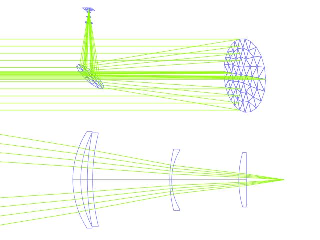
2d and 3d layouts of the whole system or groups can be rendered. The following code uses paging to render two such different views of the system:
  Io::RendererSvg       svg_renderer("layout.svg", 640, 480);
  Io::RendererViewport  &renderer = svg_renderer;

  // horizontal page layout
  renderer.set_page_layout(1, 2);

  // 3d system layout on 1st sub-page
  renderer.set_page(0);
  renderer.set_perspective();

  sys.draw_3d_fit(renderer, 300);
  sys.draw_3d(renderer);

  tracer.get_trace_result().draw_3d(renderer);

  // 2d Wynne corrector layout on 2nd sub-page
  renderer.set_page(1);

  wynne.draw_2d_fit(renderer);
  wynne.draw_2d(renderer);

  tracer.get_trace_result().draw_2d(renderer, false, &wynne);