Next: Compose, Previous: Morphology, Up: Image Processing [Contents][Index]
Segmentation
The Guile-CV procedures and methods related to segmentation.
Procedures
- Procedure: im-label image [#:con 8] [#:bg 'black] 
- Procedure: im-label-channel channel width height [#:con 8] [#:bg 'black] 
- Procedure: im-label-all image [#:con 8] 
- Procedure: im-label-all-channel channel width height [#:con 8] 
-
Returns two values: a new GRAY image or channel, and the total number of labels25.
The
im-labelandim-label-channelprocedures label foreground objects in the binary image. In the new image or channel, 0.0 indicates a background pixel, 1.0 indicates that the pixel belongs to object number 1, 2.0 that the pixel belongs to object number 2, etc.The
im-label-allandim-label-all-channelprocedures label all objects in the binary image, with no specific distinction for any background value. As a result, these two procedures will label not only the continuous background, if any, but also any hole(s). As an example, they are used by im-fill-holes, defined in the module(cv morphology), which you may have a look at for a better understanding of how it works.Two pixels belong to the same object if they are neighbors. By default the algorithm uses 8-connectivity to define a neighborhood, but this can be changed through the keyword argument #:con, which can be either 4 or 8.


Here above, left being the original image, you can see the difference between
im-label(2 labels) andim-label-all(6 labels). Note that we had to runim-thresholdon the original image first (all labeling procedures take a binary image (or channel) as their mandatory argument), for the record, we used128as the threshold value.
- Procedure: im-canny image [#:sigma 1.0] [#:threshold 0.0] [#:marker 255.0] 
- Procedure: im-canny-channel channel width height [#:sigma 1.0] [#:threshold 0.0] [#:marker 255.0] 
-
Returns a new image or channel.
Detect and mark edges using a Canny Edge Detector algorithm: (a) compute the image Gaussian gradient using sigma, (b) remove edges whose strength is below threshold, then for all remaining edges, (d) remove the non-local maxima (edge thinning) and (e) set their intensity using marker.
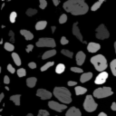
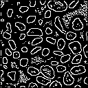

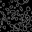
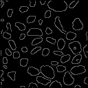
Here above, left being the original
tifimage26, you can see the difference betweenim-cannycalled using the default values, then using #:threshold 8, and finally both #:sigma 1.5 and #:threshold 8. The last example is an illustration of the use of#:marker 96.027.
- Procedure: im-crack-edge image [#:marker 255.0] 
- Procedure: im-crack-edge-channel channel width height [#:marker 255.0] 
-
Returns a new image or channel.
Crack edges are marked ‘between’ the (different) pixels of image. In order to accommodate the cracks, the resulting image or channel size must be (- (* width 2) 1) and (- (* height 2) 1) respectively.
Crack pixels are first inserted, then all crack pixels whose non-crack neighbors have different values are crack edges and marked using marker, while all other pixels (crack and non-crack) become region pixels. Here is a simple example, with two regions, a and b, and using * as the crack edge marker:
Original Inserted Cracks Final Result a b b
a a b
a a aa . b . b
. . . . .
a . a . b
. . . . .
a . a . aa * b b b
a * * * b
a a a * b
a a a * *
a a a a a
Here above is the result of
(im-crack-edge img #:marker 127), withimgbeing the 6 labels image displayed earlier.Crack Edge Images have the following properties:
- Crack Edge Images have odd width and height.
- Crack pixels have at least one odd coordinate.
- Only crack pixels may be marked as crack edge pixels.
- Crack pixels with two odd coordinates must be marked as edge pixels whenever any of their neighboring crack pixels was marked.
As a consequence of the last two properties, both edges and regions are 4-connected. Thus, 4-connectivity and 8-connectivity yield identical connected components in Crack Edge Images (the so called well-composedness). This ensures that Crack Edge Images have nice topological properties28.